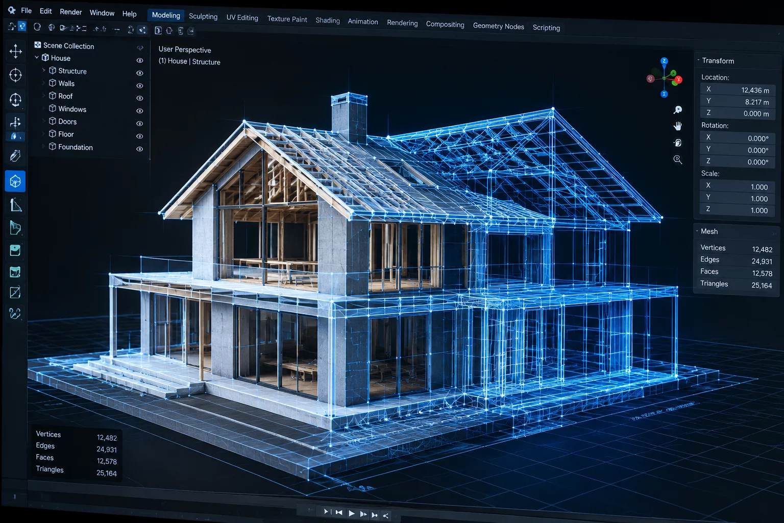
Overview & Workflow Architecture
Core 3D modeling functions for interior design. Strictly engineered to empower architects and planners with high-speed polygonal construction, automated snapping, and precise dimensional control for complex residential layouts.
Key Architectural Principle
Parametric spatial modeling links architectural wall thicknesses, floor level elevations, and door-window openings dynamically to maintain clean geometric integrity throughout all project revisions.
Detailed Step-by-Step Implementation
Building accurate internal room models begins with establishing precise boundary extrusions. The modeling engine processes coordinate data in real time, snapping structural elements to exact laser-measured millimeter grids so designers manipulate complex architectural surfaces without encountering polygon non-planar errors or inverted normals.
Custom interior fixtures integrate seamlessly into the primary floorplan using intelligent boolean operations and automated mesh optimization. This ensures lighting calculations compute smoothly across every vertex without bloating file sizes or causing viewport lag during client walkthrough presentations.
Core Guidelines
- Dynamic vertex snapping with sub-millimeter precision across multi-floor floorplans.
- Parametric wall extrusion with automated corner miter joins and thickness control.
- Non-destructive boolean modifiers for effortless window and door framing cutouts.
- Instant normal vector recalculation and automated duplicate polygon reduction.
The Advanced 3D Modeling toolset offers architectural designers comprehensive control over interior spaces. Its automated polygon reduction keeps memory overhead low while maintaining razor-sharp geometric detail across multi-room projects.
Compatible with DirectX 12 and Vulkan graphics pipelines. Recommended setup requires a dedicated GPU with 6GB+ VRAM, 16GB system memory, and multi-core CPU architecture for optimal real-time geometric subdivision.
Can models be converted between imperial and metric units? Yes, unit conversion happens automatically without stretching or warping existing furniture geometries or wall thicknesses.
Navigate to the Geometry Inspector panel, select your target meshes, and click Re-align Coordinate Frame. The system will adapt existing boundary meshes to the updated snapping grid while preserving UV coordinates.
While basic mesh manipulation runs smoothly on integrated graphics, real-time parametric subdivision and complex boolean computations perform best on modern dedicated graphics cards with active hardware acceleration.
Community Discussion
Share insights with architectural modelersNo comments yet. Be the first to share your thoughts!
Leave a Comment or Question